Russian version
AN APPARATUS FOR INDICATING GEOPHYSICAL ANOMALIES(IGA-1) BY J. KRAVCHENKO(Russia)
Contact: Victor Pricazchikov, Moscow, email: ekogeo@bk.ru
BACKGROUND OF THE INVENTION
The present invention relates to apparatuses for indication of geophysical anomalies. It is known that anomalies of radiation, including electromagnetic radiation in so-called geopathogenous zones negatively affects living organisms, and can cause negative reactions and diseases in human organisms. It is therefore desirable to determine the locations of geophysical anomalies in order to plan working sites, hospital beds, furniture and other objects in apartments and houses, garden plots, etc.An apparatus for indicating geophysical anomalies(IGA-1) has an antenna positionable over a surface to be investigated, a converter for converting a signal received by the antenna into an output signal, an indicator for indicating a determined geophysical anomaly based on the signal, and an analog-to-digital converter which also receives a signal from the antenna to convert the signal into a digital signal to be submitted to a computer.
DESCRIPTION
An apparatus for indication geophysical anomalies (IGA-1) includes an antenna which is identified with reference numeral 1. The apparatus further has an exterior indicator 2, a preliminary amplifier 3, a narrow band pulse filter 4, an amplifier of alternative voltage 6, a phase detector 7, and a pulse generator 5 connected with the pulse filter 4 and the phase detector 7. The apparatus further has an interior integrator 8 connected with a correction block 9, a block 10 for providing coefficient of feedback, an amplifier of direct voltage 11, a differentiator 12, a non lineer element 13, a control button 14, a filter of low frequencies 15, and an indicator 16.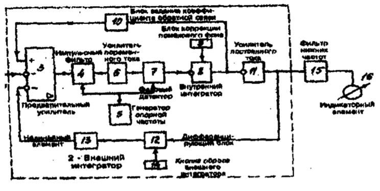 figure 1
The apparatus IGA-1 operates in the following manner:
The iniet antenna 1 is located parallel to a surface to be investigated at a required height, so that antenna 1 forms an electric capacitor with the surface and is one of its plates. As a result of the use of the antenna 1 with an extra small electrical size, or in other words of the antenna whose geometrical size is extremely low when compared with the size of wavelength received by it, there is no selective amplification on a concrete working frequency. As a result, the antenna is a broad band antenna and receives ail noise signals as a useful signal.The noise signal from the antenna 1 is supplied to an inlet of the exterior integrator 2 which operates due to the capacity nature of the antenna 1 as an indicator of an input voltage, or in other words as an amplifier of the charge of the antenna 1. After amplification of the noise signal in the preliminary amplifier 3 which has a first inlet connected to the inlet of the exterior integrator 2, the amplified signal passes through the narrow band pulse filter 4 with a band of passage corresponding lo fractions of herz. Here a separation of the frequency component of the noise signal is performed or the frequency of the pulse voltage generated by the generator 5 which can be readjusted.
After amplification of the signal in the amplifier of the alternating voltage 6, the amplified signal of frequency component of noise is supplied to the first inlet of the phase detector 7. The output signal of the latter is proportional to the value of phase difference between the base signal of the generator 5 and the separated frequency component of the signal received by the antenna 1, or in other words of the noise signal.
Thereafter the signal of phase difference is supplied to the input (inverting) of Ehe integrator 8, whose non inverting input receives the voltage of correction of the noise background from the output of the correction block 9. The resulting signals supplied from the output of the interior integrator 8, being weakened in the block 10 of the coefficient of the Feedback, which forms a voltage divider, to the second non inverting input of the preliminary amplifier 3, where it is subtracted from the input noise signal.
Therefore, due to the embrace of the second interior integrator 8 by a loop of the feedback, the whole path from the input of the preliminary amplifier 3, to the output of the integrator 8 operates as a smoothing filter of low frequencies, which is necessary for smoothing of pulsation at the output of the phase detector 7 and for accuracy increase of conversion of the value of phase shift into a direct voltage. The value of coefficient of transmission of the block 10 in the loop of feedback also determines the coefficient of amplification of the above mentioned path. The smooth voltage which is proportional to the phase difference is additionally amplified in the amplifier of direct voltage 11, and through the differentator 12 which is a capacitative feedback and reacts to the change of this voltage, as well as through the non linear eement 13, it is supplied to a third inverting input of the preliminary amplifier 3, where it is also subtracted from the noise voltage.
Therefore, after the working positioning of the antenna 1 immovably and parailel to the surface to be investigated, the phases of oscillation of the generator 5 on the one hand and the frequency component separated by the pulse filter 4 which is equa as to the frequency to the oscillation of the generator 5, as a rule are not equal. As a result, at the output of the phase detector 7 a voltage is produced, which is averaged by the indicator 8 with the first loop of feedback through the block 10 and provides a voltage whose level is proportional to the value of the phase shift. This phase shift is accepted as a noise background and is compensated by the voltage from the output of the correction block 9 deducted from it, which voltage from the output of the block 9 is regulated to the value of a complete compensation, so that at the input of the integrator 8 the value will be equal to zero.
After this, the button 14 which short circuits the capacity of the differentiator 12 zeros the integrator 2, so that the voltage at the output of the filter of low frequency 15 and correspondingly the indications of the indicator 16 are equal to zero.
Then the working movement of the antenna 1 is performed in direction of search, parallel to the surface and with a constant speed. When the antenna 1 enters a zone of electromagnetic anomaly, an increase of the phase difference relative to the value accepted as a noise level occurs. As a result, the integrator 18 is disbalanced, and its outlet voltage appears, which is proportional to the increase of the phase difference. This voltage is amplified by the amplifier 11 and is supplied to the blocks of the second loop of feedback 12 and 13.
When the increase in the phase difference at the output 11 is small and does not exceed a zone of non sensitivity of the linear element 13, for example in the event of natural spatial fluctuations of the field which constitute noise, or on the border of the electromagnetic anomaly, the second loop of the feedback is opened. As a result, only the direct path antenna 1-indicator 16 is operating, the integrator 2 is turned off and does not integrate, and the voltage from the output of the amplifier of direct current 11 is supplied through the filter 14 directly to the indicator 16, Oscillations of the pointer of the indicator 16 are proportional to instantaneous phase increases. This deviations of the pointer of the indicator 16 are reversible, if the antenna 1 is returned back to the initial position.
In the case of entry into the zone of electromagnetic anomaly, the value of phase difference of separated frequency component from the output of the pulse filter 4 and oscillations from the output of the generator 5 increases. This leads to an increase of the area of pulses at the output of the phases detector 7 and to an increase of the level of voltage of the output of the integrator 8, proportional to the value of phase shift. As a result these changes are transmitted through the differentiator 12.
If the voltage of its output exceeds a zone of non sensitivity of the element 13, the loop (second) of feedback which is composed of the differentiator 12 and the element 13 is closed. As a result, the exterior integrator 2 is turned on and starts integrating of the selected phase difference. If the phase difference does not disappear, then at the output of the element 11 a signal increase occurs up to the value of the saturation voltage of the element 11. This voltage is supplied through the filter 14 which fitters out jump voltage during transitory processes, to the input of the indicator 16 and is indicated on it.
Therefore it suffices to have a very small value of phase difference which exceeds the zone of non sensitivity of the non linear element 13, border to cause deviation (turn) of the pointer of the indicator 16 to the limit.
A selection of the value of the integrating capacitor of the integrator 2 in the block 12 is performed based on conditions of compromise between the value of the total coefficient of amplification, (the lower is path, the greater is coefficient of amplification) and a sufficiently long time of integration for comfort of registration (the greater is capacity, the longer is the time of integration).
As can be seen from Figure 2, the apparatus has a case which is identified with reference numeral 21. All above mentioned units of the apparatus are accommodated in the case 21. The antenna 1 is attached to the case 21.
The apparatus further has a hollow arm which is identified with reference numeral 22 and accommodates a plurality of batteries 23. A grip 24 is connected with the lever 22 and provided with a release button 25 for turning on and off of the apparatus. At the end which is opposite to the case 21 the Sever is provided with an elbow clamp 26 and a handle 27.
In addition an analoc-to-dlgital converter 29 is also accommodated in the case 21. The same signal which is supplied to the pointer-type indicator is supplied also the analog-to-digital converter. A digital signal is obtained at the output of the analog-to-digital converter and is supplied to an input of a computer through a cable 30.
A computer 31 can be also a part of the apparatus. The computer 31 receives the digital signal through the digital signal cable and, in accordance with a program, produces a three dimensional image of a space to be investigated, so that geophysical anomalies found in the space are represented by spots, lines, ore columns.
Finally, a printer 32 can be connected with the computer 31. It prints an image in a real scale.
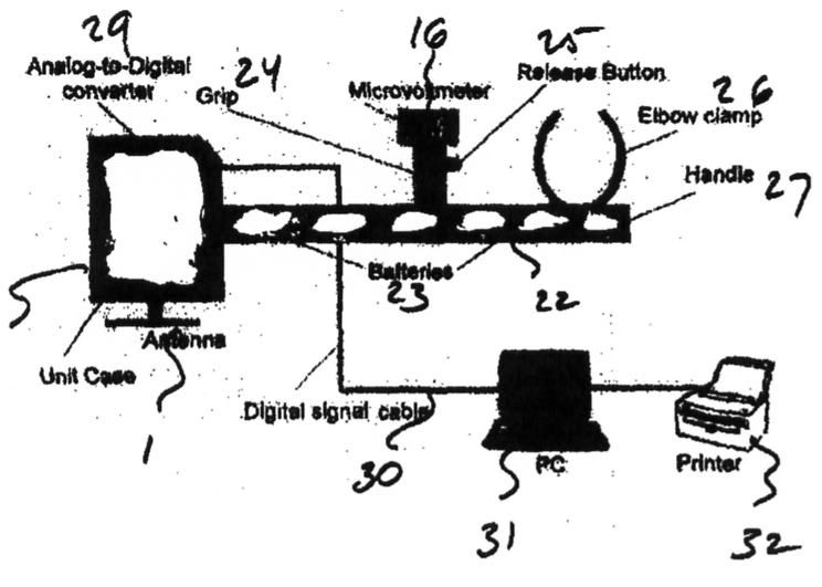 figure 2